Small Component, Big Protection: How to Safeguard Your USB-C Ports
Vic Liu, Sopha Tong | AN085
The USB Type-C interface has become the standard for data transfer and power delivery across a wide range of devices. However, with its increased capabilities come significant risks, particularly from Electrostatic Discharge (ESD) and Short-to-VBUS events. Protecting your devices from these risks is crucial to ensure longevity and reliability. The RT1735 USB Type-C 28V EPR Protector from Richtek offers a comprehensive solution to these challenges. This application note outlines how to implement the RT1735 to safeguard your USB Type-C ports effectively.
1 Understanding the Risks of USB-C Port Connection
1.1 Key Differences of USB Type-C Compared to Legacy Connectors
The USB Type-C connector differs significantly from older Type-A, Type-B, and Micro-B designs. Its symmetrical, reversible design allows insertion in either orientation, with a compact size of just 8.4mm × 2.6mm and a 24-pin configuration. In contrast to USB 2.0’s 2.5W and USB 3.0’s 5W power delivery, USB Type-C supports over 100W, enabling both fast charging and high-speed data transfer.
1.2 Two Major Challenges
1. Reduced Pin Pitch Increases Short-Circuit Risk
USB Type-C features a 0.5mm pin pitch, significantly smaller than Type-A’s 2.5mm, making it more susceptible to short circuits due to foreign objects or improper insertion angles. This risk is especially critical for SBU and CC pins, which can only withstand 5V, as they are positioned adjacent to VBUS pins carrying up to 20–28V and 5A. A short circuit could lead to severe damage to sensitive components.
2. Non-Compliant Cables and Adapters May Damage Internal Circuits
Some USB Type-C power adapters bypass USB Power Delivery specification and deliver output voltage 20–28V directly, exceeding the system’s designed voltage tolerance (e.g., 5V). This can result in permanent damage if the system does not have proper protection. To reduce these risks, Overvoltage Protection (OVP) and Electrostatic Discharge (ESD) protection are essential for system reliability.
1.3 The Two Common USB-C Connector Damage Issues are Electrostatic Discharge (ESD) and Short-to-VBUS Events
1. Electrostatic Discharge (ESD) Events:
ESD occurs when a sudden flow of electricity between two electrically charged objects caused by contact, an electrical short, or dielectric breakdown. The USB Type-C port, being an external interface, is particularly vulnerable to ESD, which can damage the port or the internal circuitry.
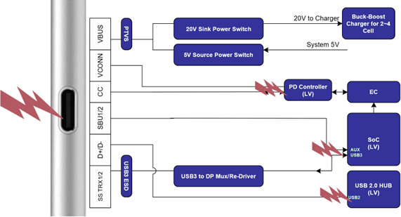
Figure 1. External Protection Switch Offers USB Type-C System ESD Defense
2. Short-to-VBUS Events:
As USB Power Delivery (PD) technology evolves, the VBUS voltage is 20V under the PD3.0 SPR standard, whereas it can reach 28V or higher under the PD3.2 EPR standard. A short circuit from VBUS to adjacent pins can cause irreversible damage.
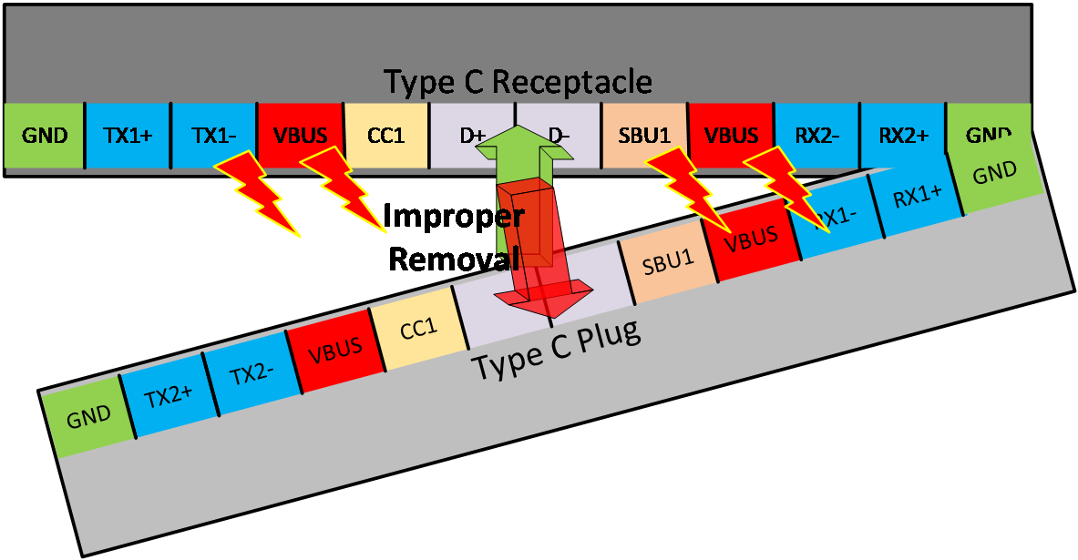
Figure 2. Angled USB Plug Removal may Short VBUS with SBU or CC Pins
2 How to Prevent the Risks
In Type-C applications, to reduce the above-mentioned over-voltage and ESD risks, the RT1735 can be placed in series between the Type-C port and other application circuits in the Type-C system to provide both over-voltage and ESD protection. The following Figure 3 illustrates the Type-C PD system with the RT1735 protection circuit.
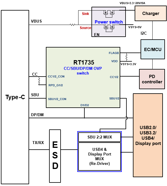
Figure 3. Adding RT1735 Protection Circuit in Type-C Connector Applications
The RT1735 provides IEC61000-4-2 contact discharge protection of ±8kV and IEC61000-4-2 air discharge protection of ±15kV, ensuring robust defense against common ESD occurrences. As shown in the Figure 4 below, when the Type-C port experiences an ESD event, the RT1735 can provide CC/SBU/USB IEC ESD clamp cell protection.
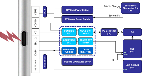
Figure 4. External Protection Switch Offers USB Type-C system ESD Defense
Due to the close pin spacing of Type-C connectors, the VBUS pin may short to CC or SBU, increasing the risk of damage. The RT1738A can be used in PD3.0 SPR VBUS 20V applications, while the RT1735 is suitable for PD3.2 EPR VBUS 28V applications.
Both RT1738A and RT1735 provide four-channel short-to-VBUS overvoltage protection for the CC1, CC2, SBU1, and SBU2 pins of the USB Type-C receptacle. When the input voltage exceeds the overvoltage protection threshold, the RT1738A/RT1735 rapidly turns off the internal switch within approximately 100ns, preventing high input voltage from damaging the terminal system. Once the CC/SBU input voltage returns to the normal operating range, the IC reactivates the switch.
3 Conclusion: Achieving Maximum Protection and Reliability
The RT1735 is a highly efficient and versatile USB-C interface protection IC designed for applications up to 140W, while the RT1738A is suitable for USB-C applications up to 100W. Both devices provide comprehensive overvoltage protection, over-temperature protection, and electrostatic discharge (ESD) protection, ensuring stable and reliable system operation even in harsh environments.
With its fast response time and low power consumption, the RT1735 is particularly suitable for computer monitors, gaming laptops, and docking hubs. Its compact package and flexible design allow engineers to easily integrate it into various USB-C applications, shorting product development time.
The RT1735 and RT1738A are both high-performance protection solutions. Designers can choose the appropriate product based on application requirements to ensure the high reliability and long-term stability of USB-C interfaces.
The above summary concludes the contents covered in this application note. To stay informed with more information about our products, please subscribe to our newsletter.